I’ll be back…

I know that some people around the world got used to read my dummy posts… I’m proud of that, and sorry I had to stop to this blog.

I moved around a lot, from town to towns…

In between, ESP32’s esp-idf is =well baked now, I worked on capacitive humidity sensors, as well as home-made resistive ones…

Please expect some updates in the next few month…

Saturday fun : playing with automatic watering system & calibatring sensors

Abstract : Winter is^W^W Holydays are coming ! I want my six plants to be keeped well watered — even if I go away from home for a w hile. Actually it’s prototyping, because the 10L tank i’m using isn’t big enough to provide needs for a long while. In this system are also included a flow sensor that counts the liquid quantity delivered to plants, and we will first discuss moisture sensors I played with.

Soil Moisture Sensing

To go quick on hardware, I got this kind kind of stuff :

moisture_sensor

I won’t spend much time to explain how to use them : with Arduino API just analogRead() the analog pin of the sensor (in this case, the sensor is used as voltage dividor). With AVR flavoured C, just enable ADC and use it as described in datasheet.

NOTE : The sensor includes a varistor and an IC (probably an OpAmp for valtage comparison), to provide a custumizabe threshold detection on a (for me) superfluous digital pin.

One “fun fact” to note : at first, I tried to use analogRead() from a NON-arduino program… (Just like I was using the Arduino Serial class in non-arduino programs in the past, with full success). But in the case of analogRead(), I could not get a single meaningful value, until I realized that it was beacause i don’t pass trought the Arduino’s main(), the function that calls setup() and then loop()s, which also sets to 1 the ADEN (ADc ENable) bit, even if the datasheet advise to set it only when using the ADC (mainly, to save power) !.. NOTE : Actually, this is done in the “wiring” module which didn’t change much recently I guess !..

Further that, it’s just analog reading. I did some experiments with a glass of water at various level of filling, and the analogRead() value seemed linearly correlated… All values were lower when adding liquid fertilizer, which match expectations : fertilizer contains ionic particules that improve ElectroConductivity of water, lowering the variable resistance of the soil in regard of a constant resistance : voltage division gives lower value, so does analogRead().

In conclusion

Such detector are easy to make D.I.Y. Further it could be great to a read the mean / sum of two variables resistances : one in the top of the pot, one at the bottom. Unsure if it would improve efficiency, but can be a leading idea for DIY “smart-pots” receiving auto-watered plants…

Auto-watering : it’s powering a pump when soil is dry, but not only !

Here is my strange (and somewhat dangerous) setup this  day :

Link to full size image

saturdayfun_watering1

  • A. This laptop is in a dangerous situation (actually not, it’s only “posing” for the picture !). Its role is to program Arduino borad and display measurement each sec.
  • B. Arduino is “sensing” the flow throught the device that is cartoned in C. But pay NO attention to the breadboard, it only mechanical (mainly fixing floating bus wires, but also provide more friction/inertia to arduino board iself…)
  • C. the sensor flow must stand vertical, that why it stands in a carton. Quick and dirty but this worked four the few hours of the experiement.
  • D. This is the “pump” output/reductor. The circuit between pump and this very part excluded ; costed me few hours digging in a harware store, after a lot of worring… I found a suitable solution, involving a 12 mm tube that fit my 15W pump output, and two pieces that allow adaptation on this given input for the watering system (delivered in watering kit). See photo below for more details.
  • E. This stuff thightens the carton and the tank. The sensor is NOT in-between.
  • F. I plugged a T connector and 2 ‘random-lenght’ tube to simulate some hydrolic resistance, BUT multiple output // parallelisation… Did not calculate anything, sure that a complete system will have more resistance (unsure, just an intuition).
  • H. This cat has lost his keys because he was too drunk the night before… He’s still hanging around my house, but pay no attention to him, he will leave soon I guess !


Hack “DATA”

I had absolutely no clue of the output DATA signal waveform. I was guessing a short up or downrising pulse. I was wrong !

Hhaving a look on the oscilloscope to inspect that “DATA” wire. and I got a very clean square wave with a (looks like) 50% duty cycle which seemed perfect for detection. Also I had to setup a low time base to see the square, which gave me an order of frequency (about 40Hz in my system). So write, compile, and dowload that :

#include <avr/io.h>
#include <avr/interrupt.h>
#include <util/delay.h>
#include "avr_uart.h"


// === TIMER1 ISR =========
int timer1_macro_counter = 10;
volatile unsigned char tick;

void setup_TIMER1() {
  DDRB |= (1 << PORTB5); // set LED pin as output
  TCCR1B |= (1 << WGM12); // configure timer1 for CTC mode
  TIMSK1 |= (1 << OCIE1A); // enable the CTC interrupt
  OCR1A = 25000; // set the CTC compare value
  TCCR1B |= ((1 << CS11) | (1 << CS10)); // start the timer at XXMHz/64
}  // XX == 16 MHz (arduino)

ISR(TIMER1_COMPA_vect) {
  timer1_macro_counter--;
 
  if (!timer1_macro_counter) {
    tick=1;
    PORTB ^= (1 << PORTB5);
    timer1_macro_counter = 10;
  }
}
// ----------------------

// === INT0 ISR =========

volatile unsigned char flow_counter = 0;

void setup_INT0() {
  DDRD = 0x02; // bit 2 is 0 (PORTD2/INT0 as INPUT), bit 1 on (TX=>output), 0 off (RX=>input)
  EICRA=0x02; // EXT_INT0 on falling edge.
  EIMSK=0x01; // enable INT0
}

ISR(INT0_vect) {
  flow_counter++;
}
// ----------------------

void main(void) {
  cli(); // at least timer1 (16bits) setup needs atomicty
  stdout = &avr_uart_output;
  stdin = &avr_uart_input_echo;
  avr_uart_init();
  setup_TIMER1(); 
  setup_INT0();
  sei();
 
  printf("Pump flow sensor, welcome\n\n => ");
 
  while(1) {
    if (tick) {
      cli(); // Avoid race conditions
      int tmp = flow_counter;
      flow_counter = 0;
      tick = 0;
      sei(); // restart interrupts
      printf("%d\n", tmp);
    } 
  }


saturday_late_work

Here you can plainly see the relevant hardware solution I found to connect a 12mm pump output to a 1/4 inch tube… How do you say “Casse-tête chinois” in your own language ?

This hydrolic circuit as 6 outputs. Its flow has to be tested, yet.

Conclusion

The experiment gave on my screen 644 measures (10 minutes, 44 seconds), but more, it gave about 300.000 cycles on DATA wire (300724 exactly), for barely a bit more than 9L, which gives me a factor of 0,3mL / Hz… If you want liters per minutes, the coeficient is 0.018. I found this consistent with the coeffcient found out by another Amazon Custmer on a sililar, but quite different device, here, he said:

Post Scriptum : Go “naked” at your own risk…

At first I tried to make INT0_vect an NAKED_ISR… As (des-)Assembly code was touching “just” r24 & r25 registrers (using adwi 16 bit addition opcode) I pushed & poped those registers (reverse order OBV) around the incrementation.

It was clarly not enought !

The behaviour was surprizing : while no pumping, LED blink and printf() were regular as the clock, but as soon as the pump runned, printf() was called “randomly”… I added the LED blink inside IMER1_COMPA_vect after some investigations. The LED blink was OK.

By writing those lines, I realise I forgot about restoring SREG ! It’s probably THE source for all my troubles… Unsure, but I bet !

Indeed, the Status REGister contains status bits (OK so far). Some of those bits are used by latter assembly instruction, to “know” the result of a former one. It’s a general principle, valid in every CPU (AFAIK).

On the other hand, I soon realized that in such simple code ; only “if(tick)” could misbehave. Thus, meaning probably that ‘tick‘ variable memory space was trashed elsewhere (I do multi-thread programmation, and debugging, as a day-job, so,  I know a bit about that). But in this case, the timing was secured, I even added superfluous ‘volatile‘ keywords… But cli/sei should be enought to avoid any problem !

In my first version of ISR(INT0_vect, NAKED_ISR), I was NOT saving/restoring SREG !

THAT could expain “if” instruction execution got in trouble, when INT0 ISR occurred in-between and trashes SREG state.


openPowerSwitch 2/… : Playing with ethernet interface and setting-up a test env

Abstract : First experimentations with an ENC28J60 (ethernet MAC+PHY interface from Microchip). Setting up a minimal server, and test it in an isolated network environment.

Introduction

As usual, let’s introduce the hardware. ENC28J60 is a 10 base T MAC+PHY <=> 40MHz SPI interface. In runs under 3.3V but is designed to handle 5V logic seamlessly. It embeds 8Kb of RAM to buffer ethernet frames.

enc28j60

An ENC28J60 module for prototyping. Many clones, in various form factor, are available.

Let’s review the pinout of the module (if not exhaustive, rather complete for most purposes).

  • CLKOUT : a configurable clock source. By default the modules start clock it @12.5MHz but it can be configured/scaled, by writing chip registers through SPI commands.
  • INT : Interrupt pin
  • WOL : the “Wake On LAN” pin, usable to wakeup the interface controller in sleep mode.
  • SO : Slave Out (MISO)
  • SI : Slave In (MOSI)
  • SCK : SPI ClocK
  • CS : Chip Select. Hold low if you want to enable the chip as the slave listening the master
  • RESET : No comment.
  • Vcc : NOTE TO MYSELF : PLS read datasheet / check module wiring and DO NOT write crap here instead
  • GND : The ground.

If you lacks knowledge about the SPI protocol, let’s review the basic :

Back to basics : SPI

SPI is an electronic protocol that allows full duplex (read and write simultaneously) serial communication between two chips.

The master “clocks” the line, and on each tick each peer reads the bit provided on its input line, and provides next bit to write on its output line. Communications can be single sided, though. For instance, master can issue a “register read” command to the slave (which, in  the meanwhile does not write anything to the master). While the slave answers, the master has nothing to say to the slave. Then the communication ends. HALF DUPLEX !

Maybe this chip is able to do real full duplex but I’m unsure. Anyway, the driver presented in this article does NOT. (It was a bit curious to me at first to realize that the chip acheives most communication NOT taking advantage of full-duplex. So why SPI ? Because it is CAN BE fast. And presently IT IS.)

If you want more information, or want a refresh of your already acquired knowledges, it invite you to check this damn good article on Hackaday.com.

Software driver for the ENC28J60

The datasheet for ENC28J60 is pretty well written and clear, but it is always challeging to write such a driver library “from scratch”, even with a good datasheet. By the way of discussing about full/half duplex on #avr (on freenode’s IRC), @Lambda_Aurigae, advised me to have a look on the tuxgraphics project.

I did and found what I would call an “half driver” : the basic parts of the datasheet are implemented (…roughly, the half…) but not the advanced features, and among them, what seems very important to me, the interrupt part.

In pratice, this driver is the bare minimum to start with, and also sufficient to integrate with already existing higher-level software (but let’s discuss this in part 3).

After few digging, I forked a github repository that contains an “UDP spoutnik” (beep, beep, beep !). IIRC I did a few Makefile re-working to fit my env, but it compiled, installed and runned seamlessly.

Implementing

I caugh the UDP packets using this setup :

oPS_20170219

And, not shown on photograph, I used a TU2-ETG (that is, an ethernet-to-USB converter) to isolate the prototype. I just captured traffic on the network interface related to this device with wireshark, and could see the beep UDP packet spawing every second !

The workbench can be schematized by the following:

setup_ops

A linux laptop is connected by USB to an Arduino and an TU2-ETG device, with is a network interface. The net dev is connected to the ENC28J60, which is powered by and connected to the Arduino. Finally a relay board is connected to the Arduino : the aim is to control the relays using the network interface. NB : INT (magenta) wire is not used yet, as far as I know, by the driver (eventhough it enables the interrupt flag, it does not implement a callback… WTF ? But there is room here from improvment)

That allowed me to validate both at once the tuxgraphics simple driver and my ethernet module ! This was a really happy evening I remember ! Double headshot ! But I did not much by myself, so let’s work now…

Toward a real test environment…

Right now the TU2-ETG provides some network isolation and allows monitoring through wireshark… But this is not enough !

We want this interface to behave like a “natural network”, and, mainly, by providing (coherent and consistent) answers to DHCP request.

I dediced, that, while 192.168.0.0/8 was my main network, this interface will behave as a 192.168.2.0/8 network. The laptop is 192.168.2.254 on this network, and we want it to serve DHCP requests.

So we have to install the dhcp SERVER daemon package (link is for Arch Linux, but ths package exists for any Linux distribution). After the installation, on my side the configuration was as simple as editing /etc/dhcp.conf and :

  • declaring the “normal” network on which I don’t want the daemon to serve anyone :
subnet 192.168.0.0 netmask 255.255.255.0 {
}
  • declaring the “special” subnet on which I want the daemon to act as a server :
subnet 192.168.2.0 netmask 255.255.255.0 {
   range 192.168.2.2 192.168.2.252;
}

after that it was possible to start the interface and the server…

$ ip a show
[...]
5: enp0s20u6: <NO-CARRIER,BROADCAST,MULTICAST,UP> mtu 1500 qdisc fq_codel state DOWN group default qlen 1000
    link/ether 00:50:b6:??:??:?? brd ff:ff:ff:ff:ff:ff


$ sudo ip link set enp0s20u6 up
$ sudo ip address add 192.168.2.254 dev enp0s20u6
$ ip a show
[...]
5: enp0s20u6: <NO-CARRIER,BROADCAST,MULTICAST,UP> mtu 1500 qdisc fq_codel state DOWN group default qlen 1000
    link/ether 00:50:b6:??:??:?? brd ff:ff:ff:ff:ff:ff
    inet 192.168.2.254/32 scope global enp0s20u6
       valid_lft forever preferred_lft forever


$ sudo strace /usr/bin/dhcpd -V -4 -q -cf /etc/dhcpd.conf -pf /run/dhcpd4.pid


Testing the DHCP server

As we can test the server using our “under development” module, lets use some of that raspi laying around !! I just booted a minimal system, connecting the raspi to a monitor and a keyboard, and eventually to RJ45 “auxilliary network”, after boot completed.

raspi_is_DHCPed_by_laptop

Conclusion

I started to integrated uIP stack on the workbench prototype, and I have hope it will work soon ! I guess the problem I’m facing right now is about braodcast and packet filtering at the ethernet module level… So I hope to solve it by tweaking the network_init() function that initialise the eth chip…

I saw (in wireshark) the DHCP server offer a valid adress on the subnetwork to my work-in-progress device requesting one… But sadly, the latter did not take the offer into account ! Look at traces, it seems the interface does not see any packet (at least… matching its filters…)

setup_photo


DIY Project : An “openPowerSwitch” 1/…

Abstract : Prototyping a DIY “powerSwitch”, i.e. an ethernet (then HTTP/TCP/IP) controlable device, that switches AC (220/230V) plugs — Part one : getting a prototyping board with relays, and evaluation.

Introduction, project context.

At work, I sometime use some special mains named “e-PowerSwitch“, basically some switched plugs that one can control from network (or serial RS-232 link for the commercial product we have at the office).

Such devices are quite expensive. When, on an occasion, my own was preempted by another project, I decided that nothing in such a device is hard to do nowadays. It was, then, a luck to design a prototype (and learn new things, like, why not eventually Kicad prototyping, and produce a one-block PCB for this project).

Driving electromecanical relays with GPIOs

My first toughts, initiating that project, were about all hardware details about electromecanical relays, in order to (maybe, eventually) produce my own design of a board. But, Keep cool : I quickly ordered an 8 relays “all-incluse” board for 7€, quick delivery included !

Let me quote some facts, I learned last years about electronics, and switching relays from an MCU.

Typical problems are driving current into the relay coil, which is often too much for an MCU… A typical solution is to hook a switching transitor to  draw the current into the coil ; but then it leads to another problem : when the relay switches off, the electromagnically stored energy flows back and can then damage the transitor. A “free-wheeling” diode that drive the current back to Vcc (it actually flows back into the coil, and the diode, and so on until energy is dissipated).

npn-relay-switch-circuit

Simple design for MCU/relay interface. (Click image for source and more info)

There are better implementations using MOSFET, for instance…

Relay board overview

The 7€ board I got for the prototype even uses optocouplers for GPIO voltage adaptation (versus a required 5V Vcc for the relays).

ops_relays

There are 11 input pins for this board (but 13 exposed ! let’s explain tha t8 pins are input pins for relays. There are pulled high internally and need to be pulled down to switch the related relay ON. The main “bus” of the board exposes the 8 inputs, Vcc and Gnd, 10 pins.

A second “pinholder” is very badly designed… But it’s the same on many clones you’ll cross on the interwebz. The wrongest choice here is to expose GND near Vcc were a jumper is provided… 1/10 inch wide, perfectly fitting.

jumper_danger

Never, ever, neither…

Either you SHORT the 5V Vcc to the optocouplers ref voltage, either, you provide another voltage ref, say 3.3V for coupling a rapsberry pi (though you still need to provide a stable 5V Vcc !)… But do NOT SHORT Vcc and GND. Your voltage supplier will acknowledge your efforts.

A little test implementation

ops_20170219_relays

Very simple, only connect Vcc, GND to the Arduino board power output, and A1..5 pins (avr’s PORTC pins 1..5) to relays board IN1..5.

The code for this sketche can be found on Github (as promised, this time I did not use the Serial class from Arduino API).

Conclusion

We have a suitable board to start the prototype and drive 220V AC mains.

Experimentation (with no load) showed me that something is poor in my connections, at least two “Dupont” cables, as relays 2 and 3 (1..5 plugged) were twitching (led blinking and switching sound… It was quick ! good relays !)

Now let’s implement a minimal TCP/IP stack upon an hardware ethernet controler, and we’re nearly done with that !

Everyone hail to the ESP32

Introduction

Short article this time, I didn’t order the hardware so far, but there is some rumble about the next-gen chip from espressif, the ESP32.

The Hardware

I don’t have much to say on the hardware yet, what I know is that it will be even faster, with more memory, and … a 2nd CPU core ! I hope the SDK will provide some API (even if poorly documented, just evocated in the docs like the sniffer mode right now for ESP8266… /me has to play with the latter !).

Some words about the SDK… Not quite baked yet 🙂

The firmware, esp-idf (IDF like IoT Development Kit) is written in collaboration with the community. I just hope, given some discussions on FreeNode/#ESP32, that the API will still provide real asynchronous methods, and will not drift too much on an Arduino-like side… I can cope with a pinMode() / digital{Read|Write}() API for the GPIOs, but I don’t want an SPI.write() that would wait for the SPI transfert to be finished to return me the ‘OK error code’, whereas the main CPU has nothing to do meanwhile ; after it set up the registers of SPI peripheral and a the DMA’s ones…

I don’t worry much because @bvernoux, which is an active user in #ESP32 and in SDK development (didn’t check, but, I guess so) ; is the one who pointed out there was a DMA facility (at least, when I was reading the chan).

Futhermore, the esp-idf repository is “leaded” by @projectgus which was the main developper of esp-open-rtos ESP8266’s SDK ; and was hired / founded by espressif to “sheppard the community” (but I maybe misunderstood something, forgive any mistake !)

So, even if the hardware was officially released yet (but was hard to order ! Given some testimonials on the IRC), the firmware itself it still in the oven ! It is expected to be served hot in Q1 and probably “safe to eat without burnings” for any serious C coder in Q2.

Awards

I knew that at some point in time, chineese ingineers would come to produce something great. Chineese people “led” the world economy for centuries, the two last where an ‘anomaly’ in regard of history, on this particular point. I hope earnings will bring some more freedom to China, and not China will restrict our freedom if we pay them.

Anyway, i’m not here to talk geostrategical economy, but about politics, I have to bow before espressif’s choices, involving OSS community for the esp-idf development !

Conclusion

I know that The Pragmatic Programmer book teach to be an early adopter, but, first, I have to do something with the hardware I already ordered, not only flash some demo ; second, the firmware is definitly not ready now, the hardware is expensive and will drop after christmas/new year with a new — and probably bigger — wave of production from espressif.

So I’ll wait few month before ordering the hardware.

Afterword : the first real IoT chip ?

I forgot something in the “hardware” chapter, its about protocols supported. (Note the ESP familly is served in different flavour support various RF links, by various integrators).

bvernoux stated once on IRC that ESP32 is the “first” IoT chip, really.

His word (I ask him and he kindly answered me) is because of power consuption : ESP32 has BLE, and presumably more efficient power saving modes than previous generations, allowing it to run a looooong while on batteries.

Really 🙂

Setup a development environment for ESP8266

yodawg_electronics

Abstract : Setup an ESP8266 dev board, taking advantage of it USB/UART interface to flash new native applications/firmwares (and, possibly, bootloaders?).

Context and expectations

So I recently order a “NodeMCU devkit”, and here it is :

My NodeMCU devkit board model, very same revision (image from Big Dan’s Blog)

To me it looked to provide what I basically expects from ‘Arduino’ boards : an MCU breakout, and some USB/UART connectivity through an FTDI-like chip (UART to USB), allowng programming the chip. It is even supported in Arduino IDE, but, let it to the noobs.

What I want with ESP8266 is to code in C(++) some custom firmware application, using my favorite editor and tools, build it through a makefile, and upload with a convinient command, (possibly using ‘make upload‘, as do with my duino, given the USB device is specified in the project’s makefile).

But dude, why the $#*& do you want to use this MCU ?

it integrates WiFi, as you can see on the picture.

  • it’s harvard architecture internally, like an AVR (but uses Instruction RAM — and ROM for storage — instead of fetching from program flash).
  • Also can run external program, but slower, since it needs to fetch instructions from external storage.
  • It’s 32-bit (arduino’s AVR are 8-bit), runs at 80 MHz (most 8-bit AVR are –officially– limited to 20MHz, and Arduino boards are clocked @16MHz),
  • It has 64 KiB of instruction RAM, 96 KiB of data RAM, where atmega328p (Chip of Arduino Uno) has 32KiB ‘PGM’ flash for code and 2KiB data RAM

Read more about this chip on wikipedia

The core CPU is far superior to 8-bit AVR one, as sold by Atmel.

At exactly the opposite of what most hobbists are doing ; i.e. using Espressif native firware of the ESP as a back-end peripheral, sending textual command to it from an Arduino-lib “powered” 8-bit AVR, through a 115200 (or even 9600 — sick !) bauds link…

On my side I want to takeover the chip firmware ! And maybe, but only if needed, use AVR8 as an “auxilliary” chip. I still like AVR and will use it in my first PCB design, when I’ll have finally learned to use KiCAD and enough time to implement the prototype. Also, AVR8 is still the best choice for  low power designs (IMHO).

What is needed step-by-step

I browsed, swimmed and sometimes sank in the massive database about ESP8266 provided by the WWW… First hours browsing for this chip are information overwhelming. After few time, one learns to recognize what is dedicated to him, what could be, what is definitively not. And enventually found a path that seems correct to reach my goal.

There are  alternative solutions (using native SDK, etc…) but the setup I describe below is (hopefully, but please let me know your feedback if any) the most “open source” flavoured one, for a greater control from the poweruser on the hardware.

Factually ; it’s easy as a piece of cake :

Install the toolchain

Just clone esp-open-sdk and build it with make. NodeMCU (the tag on the board sayed “nodemcu”, so it was my starting point) tutorial was recommanding to use :

STANDALONE=y

option, so I get suspicious about it, and noted from the wiki that as :

This is the default choice which most people are looking for, […] just [typing make] is enough.

Ermmm. Nope. Just… let me think : Nope.

We are fucking freaks using ArchLinux, not in a virtual machine, futhermore ! We are not “most people“, we want a toolchain that integrates plainly in our GNU system, as avr-gcc does already for arduino-board based developments.

Then, make STANDALONE=n is the command we want for us.

As I read in some wiki : << get prepared for a long build session, so better got a coffee >>

Let me add : and possibly a marijuana cigarette….

.oO°(   yes, even with a good connection, you will squeeze and scratch it down before the build completes, and will have time to talk to the elves. To the elves ??? That was DMT, not marijuana, dude !    )°Oo.

Anyway, 10 minutes later (yes hours, ok, dude), back on good old Gaya planet, we can acheive the second step :

Note for the noobs

HINT : after that, either make install, or simply add a

PATH=$PATH:’~/esp-open-sdk/xtensa-lx106-elf/bin/’

line into your /etc/bashrc ; ~/bashrc or any script that setups your env.

NB : If your don’t understand what you have do now, press ALT-F4 for more help.

Install an SDK

I choosed esp-open-rtos because it’s an open source implementation, the only one I noticed to emerge among the “noise” about ESP in the first hours. Also it seems active (they have a chan on freenode, #esp-open-rtos).

I’m still learning, but so far I still consider this is, at least, a powerful solution that meets perfectly the needs I expressed formerly.

Just go to their well done github repository, the homepage’s readme.md explains almost everything (and has good links, wiki…)

I was able to seamlessly use the repo examples/, and I tested (all worked more or less) :

  • serial_echo (first flashing ever),
  • access_point (setup an access_point, and serves a minimalist ‘hello world’ telnet),
  • get_http (fetches a single, simple HTTP page each 10s, reports # success/failure)

The ONLY exception is that the access_point example did not take in account the SSID and keyword I #defined in the source code… Exposing a generic “ESP_” SSID and no security.

is  — That’s the ONLY point that didn’t work (but I did no debug on this so far).

Conclusion

I was used to setup the tty device in the project custom makefile, this SDK ask it to be on the command line (ESPPORT=/dev/ttyUSBx). What a change !

To upload the program build the commaand is not the “make upload” i’m used to type but “make flash“.

I’ll go to Arkham because of this very little tweak, i’m sure ! And that’s obviously one of the Joker’s tricks…

Postscriptae :

Nota buene : postscribere is a verb (meaning “to write after”), which postscriptum is the past participle. The word “postscriptae” itself is a joke — just like scriptus was a noun, and scriptae its plural — indicating I anticipate numerous editions of the post ;°)

And… After some research, it turns out the correct terms is likely to be postscriptos.

EDIT 1 : 29/11/2016

Eventually, it is more head-hache prone to find one’s own way in this world.

First, in my opinion, esp8266 user are in big majority Arduino users (but hardcore noobs ! lol, it’s not evil, I love them too). It’s annoying when searching/browsing the web, because you can’t even filter out the arduino word. So it’s false-positive/non-relevant result overwhelming. I did not try esp-open-rtos so far, just basic examples esp-open-sdk (non-os sdk API) compilation and flash (and tweak, and reflash, and…).

Another pitfall I did not foresee, was how to flash a specific module, given its memory map. esptool.py is only semi-automated at that point, and does not the deduction for you, while I guess it could. There is a serious learning curve about correctly flashing the device. So far I limited my tests to the simpliest scenario, no serious multi-stage-bootloading, and further, no OTA udpate done yet.

Currently, i’m trying to compile esphttpd ; the aim being to reuse the libesphttpd in other projects, as it seems the top of the state-of-the-art (…not quite sure of that, but it is still a good piece of software anyway — still experimental though, I’m struggling with compilation problems right now…).
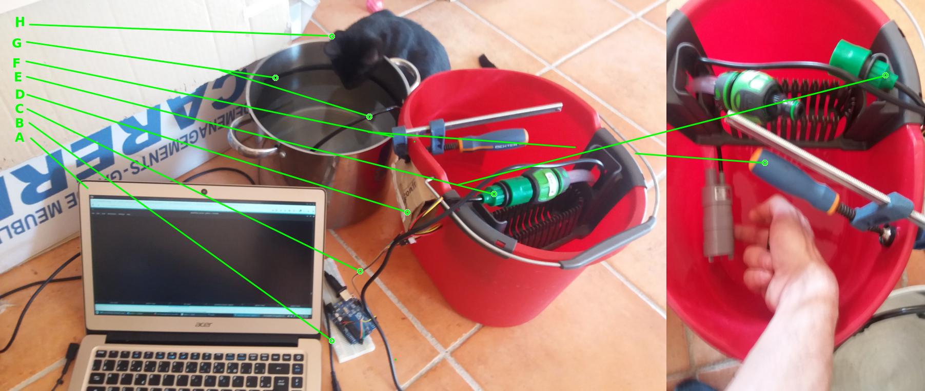
Playing with an old SRAM

Abstract : Setup an old PC SRAM with Arduino, try writes to and reads from ; then display on serial output.

Note : This schematics and code are for didactic / demo purposes only.  It would be silly to use such implementation in a real design. On the other hand, XMEM interface (AVR eXternal MEMory) can probably be used with such SRAM chip.  It will the topic of a next study. Right now I have no AVR/Atmel chip doing XMEM, only Arduino boards, sadly…

Introduction

A friend of mine recently provided me with a bunch of various electronic components (thanks Xavier !). Among them, there was IS61C64 chips : old 8K SRAM cache (picked up in an old PC : 286, 386 or so… ).

Let’s try to write to and then read from the chip’s memory bank.

For this demo I used an Arduino Uno R3 with Atmega328p, which lacks pins to fully cable the SRAM chip. I had to drop some bits on “binding”, only addressing with 6bits (64 byte values accessible, only !).

Pinout of IS61C64

Here is the pinout of this chip. I have a DIP 28 chip instead of SOJ/SOP, but doesn’t matter, i only found datasheet for IS61C64

IS61C64

There is 4 control pins : /OE, /WE, /CE1 and CE2.

How this chip works :

This is an SRAM (i.e. Static Random Access Memory). NB : the word “RAM” itself doesn’t mean much since ROM are not sequencial anymore (like magnectic tape or pattern cards). This is just a “static”, but volatile (which means RAM) electronic memory.

When MCU sets /CE1 and CE2, it can still select READ or WRITE cycle, by setting /OE (Output Enabled =  READ CYCLE) or /WE (Write Enabled = WRIRE CYCLE).

Wiring An Arduino for a Demo

Here is the wiring, it is aimed to ease the code (AVR oriented, using PORTs : B, C, & D). The goal is to ease coding by using some convention (PLEASE NOTE this is my personal inspiration under that mood, not any universial convention, nor an Atmel one) :

PORTB is for “Binding“, i.e. address, and is 6 bits wide. Could be 8 using arduino’s A4 & 5, but there on PORTC I dedicated to Control Bus. Anyone with basic knowledges in C can make this trivial extension — even “Arduino flavoured C” ! (kr-kr-kr… I’m bad, mean and evil >:)

PORTC is for “Control“, i.e. setting (/CE1, CE2, /OE, /WE) state. It’s 4bits wide.

PORTD is for “Data“, i.e. for exchanging data between MCU and the chip. It’s a byte wide.

hardwareschematics

hardware_realActual implementation

The demo code

A mini driver lib for the chip

void init_IS61C64(void) {
    DDRC  = 0x0F;  // Control bus is PORTC[0:3]
    PORTC = 0x05;  // /WE=0 /OE=1 CE2=0 /CE1=1 : IDLE
    DDRD  = 0XFF;  // Set DATA port as output by default
    PORTD = 0x00;  
    DDRB  = 0X3F;  // Only PORTB[0:5] are wired
    PORTB = 0x00;
}

void write_IS61C64(unsigned char address, unsigned char data) {
    // switch portData to read mode
    DDRD = 0xFF;
    PORTD = data;
    // write adress to portB
    PORTB = address;

    PORTC = 0x02;       // /WE=0 /OE=0 CE2=1 /CE1=0
    _NOP();             // theorically useless ! See below in the post.

     // restore 'idle' control state
     PORTC = 0x05;      // /WE=0 /OE=1 CE2=0 /CE1=1
}

unsigned char read_IS61C64(unsigned char address) {
   unsigned char data;//switch portData to read mode
   DDRD = 0x00;
   // write adress to portB
   PORTB = address;

   PORTC = 0x0A;        // /WE=1 /OE=0 CE2=1 /CE1=0
   _NOP();              // theorically useless ! See below in the post.
   data = PIND;

   // restore 'idle' control state
   PORTC = 0x05  ;      // /WE=0 /OE=1 CE2=0 /CE1=1
 
   return data; 
}

The _NOP() instructions are here to extend timing and ensure this old, maybe used SRAM, has enough time to process data. << Just speak slower to elderly >>

Theorically it is useless even with IS61C64-25N. Indeed : 25N is 25ns access time, and 1/25ns = 40Mhz garanteed ! Where most AVR chip are 20MHz max..

The main() function

Nothing spectacular here. But, for the record :

  1. I don’t understand why the 10ms delay after init is not shown in the simulation graph below. Maybe a version mismatch or something, nothing really relevant anyway…
  2. I should get rid off the crappy Arduino’s Serial class. But it doesn’t mean I’ll write in plain C.. I still like the class primitive and templates, when well suited. But I promise the next post implying UART will use something better.
  3. Unsure if it the Serial class, the way I use it, or something else in hardware (or my PC) that make me miss some data. But I recall to meet the same problem some years ago with a different arduino, PC, and OS ! So both first are best candidates.
int main(void) {
    unsigned char result[64] = {0x0A};

    // SETUP
    init_IS61C64();
    delayMicroseconds(10);

    for (int i=0; i<64; i++) {
        write_IS61C64(i, 0xFF-i);
    }

    for (int i=63; i>0; i--) {
        result[i] = read_IS61C64(i);
    }

    Serial.begin(115200);
    Serial.println("+++");
    Serial.println("IS61C64 demo\n___\n");

    for (int i=63; i>0; i--) {
        Serial.println(result[i], HEX);
    }

    int j = 0;
    while (j<256) {
        Serial.write(".");
    } // stuffing PC buffer : avoid losing meaningful data at reset
    //LOOP : do nothing
    while(1) {
        _NOP();
    }

    return 0;
}

Simulating the stuff

SRAM8K_simulationSimulAVR output in GTKWave for the code above

We have multiple discrete phases :

  • Init : the AVR runs self-initialisation  code,
  • Write : the AVR writes to the SRAM. We can see /WE keeps low during the whole phase. Other control pins are constantly switching, then indicating indicating write cycles. Binding (address) bus expose a count up. Data bus expose a count down from 0xFF to 0xC0 as expected.
  • Read : the AVR reads from the SRAM. All Control pins are switching indicating read cycles. Binding bus counts down, and Data bus stays low, because we are simulating here, so there is no actual SRAM to serve data. The aim here is just to check the AVR output pins state through time, not checking the whole design. NB : /WE switches because choosen rest state is “write”.
  • UART init : the AVR initialise Arduino’s USB link through AVR UART.
  • Pause : AVR sleeps.
  • Data transmission : through UART and over USB.

Everything seems OK.

At first I was dumbly trying to send data interleaving reads from memory. I was hoping that Serial.write() was synchronous with transmission acheivement. Stupid guess ! The first simulation quickly showed that there was a mess-up on TX (and then, RX) pin(s), which is also a Data port bus pin…

I realized (by examining SimulAVR execution logs) that Serial.write() only writes into the UART physical buffer and then returns. To ensure pin “housekeeping”, no read nor write should be issued between Serial.begin()  … Serial.end() sequence call.

Conclusion

Everything worked liked a charm on real hardware on the first try (but the UART buffer problem that lead me to print 256 ‘.’ after useful data).

Everything worked… even TOO good !

I mean : on my first try I “forgot” (and was lazy) to wire unused pin to GND (i’m software engineer, heh !)… But I also unwired volontarily Vcc and  (less volontarily) /OE:/

And IT STILL WORKED ! So surprized, I unplugged all Control Bus wires (by that very time, I realized that /OE control was not plugged on SRAM pin)… I then get the expected result, i.e. : only zeros on all  SRAM rows.

Then I believe the chip was powered but some (set of) pulled-up pin, and /OE is not quite important with this chip, at least when /WE is driven.

Going Further…

  • Using XMEM capable chip on a “bread”uino…
  • Implementing string transfer (i.e. read & write burst, holding Control bus state during whole transfer)


[The Quest for…] Atmel Studio

License and download

Here you can download : Atmel Studio.

If I remember correctly, any is allowed to downlad and use it free-of-charge (maybe while not selling AVR appliances… To be checked).

Pros and cons

Pros

Atmel Studio can be seen as a “trusted reference” for what is supposed to be the hardware behaviour — since this software is from the manufacturer.

Also, it integrates a GUI that allows step-by-step debbuging, allows display of all registers and memories (flash, eeprom, SRAM), and highlights any modification. This is very useful to quickly experiment and understand, for instance, the behaviour of a counter, how it works, controls the pins…

atmel_studio_simulator_raw

Then Atmel Studio can be great for self-teaching. Its comprenhensive GUI one can easly master with only some basic knowledges of any Studio-like tool.

Cons

On the other hand, using Atmel Studio on a day-to-day basis  can be a pain in the ass, if not driving your development. If it does… huh ? Why are you reading me anyway ?

I mean that like other Microsoft tools, is invasive and exclusive (Atmel Studio is based on MS Visual Studio… and avr-gcc ! Poor, sick world… -_-‘). For instance, while adding an existing file is a piece of cake ; I found no natural way to integrate an existing directory in a project, which arose difficulties to synchronise with git (and virtually any other VCS).

To make my pulled directory recognized inside Atmel Studio I had to :

  1. Create the directory, empty, inside Studio,
  2. Close Studio (maybe optionnal),
  3. Remove the directory on disk,
  4. git pull to get the directory  with content,
  5. Reopen Studio, import files located in directory.

This process is obviously heavy, but still acceptable for most AVR project that imply a source tree with few dozen of file maximum.

Anyway, IMO, it illustrates well the “invasive and exlusive” thing I was former talking about.

Extensibility and I/O simulation

Atmel Studio is a closed product, even if based on GCC toolchain.

Any can extend simulator using “stimuli” scripts, which syntax is summarized here.

There are few programming facilities, like triggering breakpoints (pauses the simulator), setting delays (N cycles of the MCU), assigning logical input, possibly from other register values, in a raw or using logical combinaison (bit by bit).

Stimuli files are well named : despite it’s cool to be able to stimulate our simulated core, they nearly a purely static input : no user interaction is allowed, and even no condtionnal branching of stimulation script is possible.

Conclusion

Atmel Studio is a great tool to introduce yourself or trainees to AVR world. It can even be a production tool ; it is designed to. But it drains the cons and limitation of Microsoft * Studio tools.

To someone who likes the Great Way of UNIX (to unflod this expression, please read : Master’s Foo enlightenments), and since the compiler used under Atmel Studio is GCC anyway ; it’s a great temptation to wipe this out, reboot a GNU/linux (or your favorite free OS) and use “directly” avr-gcc and avr-gdb tools.


The Quest for an AVR simulator

Do you really need a dragon ?

54_6Just a word on words…

In this post, I will often use the term simulator, as does most litterature on this topic, where the term emulator, In My Humble Opinion, should rather be used. It is because we are at a border, between pure software emulation, and electrical simulation of a board. To pass through this border, the boolean state of some bit should become a modelized electrical state of a pin.

But, AVR simulator are mainly “simulating” boolean states, using a discrete time model…

On this point, I apologize in advance for any lexical inconvience.

The concerns

When I started my try to implement a thread scheduler for 8bit AVR, and for another project after that, it quickly became an essential urge to setup a step-by-step debugger, and rather using an emulation tool :

Step-by-step Debugger :

  1. to grant fine control on program execution flow, dumping device state (memory and registers),

Emulator :

  1. to avoid flashing many times physical device with buggy-work-in-progess code,
  2. spare money of buying an AVR dragon (which allows OnChip Debugging of a physical device using avr-gdb),
  3. Use a computer, nothing more needed (AVR thread scheduling, at this step, is still at a purely theorical stage — no need to imply physical devices for now).


Browsing for it on the Web

Here is a merely complete state of the art on this topic. Ask on freenode’s #avr, if you want, I or any guy there should answer the same…

  1. Atmel Studio : it’s a proprietary tool, published by Atmel. It includes a simulator, and a debugger. The customised GUI allows to display any register or memory map, where each modified byte is highlighted. Sadly, it is runs only under windows, since build on Visual Studio. A shame, knowing that underling compiling toolchain is GCC anyway…
  2. SimulAVR : an OSS tool written in C++, and packaged as a simulator executable, but providing a really awesome framework.
    • Tcl and Python bindings are available.
    • Repository is available on github (I appreciated to be able to fork it in one click to start to integrate one or two modifs/fixes in my own repo),
    • It is designed to be interfaced with avr-gdb. ;
    • It allows dumping trace of the execution (as a sequencial log of instruction), but also VCD files usable with gtkwave,
    • For the record, Arch user, PKGBUILD is not in the AUR, but easily foundable on the web.
  3. simavr : Another awesome OSS project, written in C. It provides mainly the same features that simulAVR, but :

    • It comes with a collection of directives defined as macro to specify simulation parameters directly into an ELF custom section,
    • It is written in C. The code is awesomly clean,
    • It is integrated in Arch Linux as a Community package.
  4. AVRora : Crossed this one during my quest, but I don’t like this project : it is stalled since 12/2008, it seems to be wrtten in Java. But as existing, it is worth to quoted, and maybe to play with a bit.